
Simulation model and parameter diagram (1) :
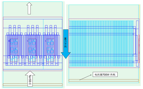
Ambient temperature: 55⁰C, reactor heat consumption: 700W
|
Photovoltaic inverter heat dissipation solution The inverter is also known as the power regulator, the process of converting direct current energy into AC power is called the inverter, the circuit that completes the inverter function is called the inverter circuit, and the device that realizes the inverter process is called the inverter equipment or the inverter. In the solar power generation system, the efficiency of the inverter is an important factor in determining the capacity of the solar cell and the capacity of the battery. The failure of the photovoltaic inverter will lead to the shutdown of the photovoltaic system, directly resulting in the loss of power generation, so high reliability is an important technical indicator of the photovoltaic inverter. Good heat dissipation of photovoltaic inverter is an important condition to ensure its high reliability operation, so the heat dissipation simulation test at the beginning of the design of the inverter has become the first issue to be considered by photovoltaic inverter manufacturers. Zerode Thermal Energy is a professional high-power heat dissipation plant in China with a professional thermal design and development team, with reliable thermal simulation, thermal testing capabilities, and a number of domestic and foreign photovoltaic inverter manufacturers carried out inverter cooling technology cooperation, to provide professional heat dissipation technical service support. Photovoltaic inverter heat dissipation solution(210KW) Simulation model and parameter diagram (1) : Ambient temperature: 55⁰C, reactor heat consumption: 700W Assuming that the system impedance is 80Pa, the diagram of the modified monomer passing through the radiator fan is as follows: 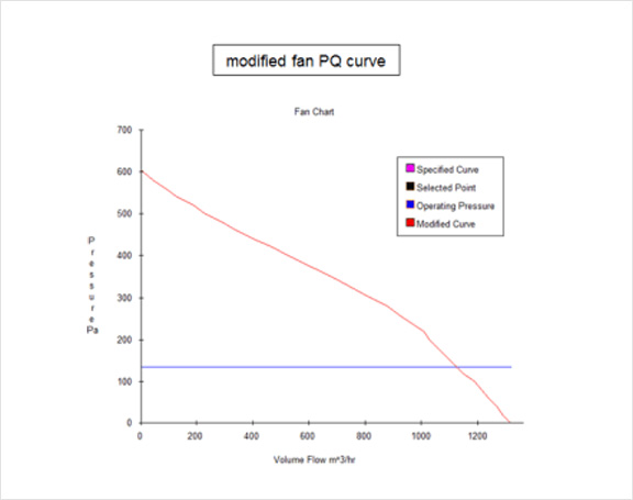 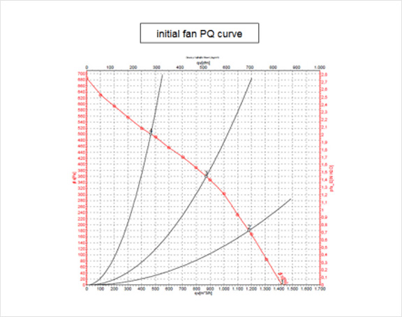 Assuming that the system impedance is 80Pa, the diagram of the modified monomer passing through the radiator fan is as follows: 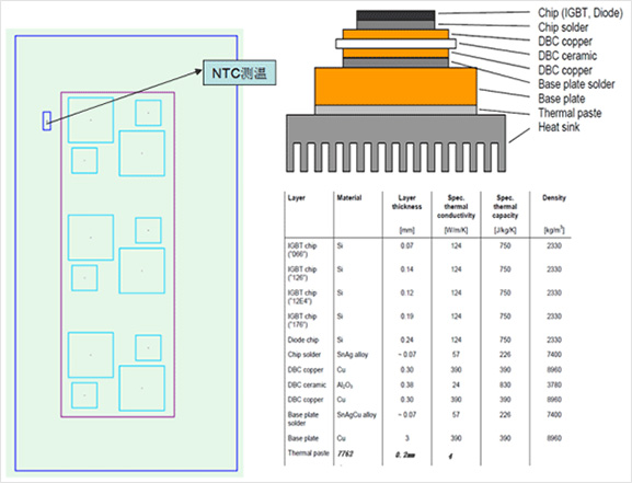 The left picture shows the internal structure of Infineon and schematic diagram of heating elements Diode:59W; IGBT:124.5W; Total:1100WW; Assume that the heat conduction medium is 0.15mm thick and K=3W/m*K。 Assuming that the system impedance is 80Pa, the diagram of the modified monomer passing through the radiator fan is as follows: 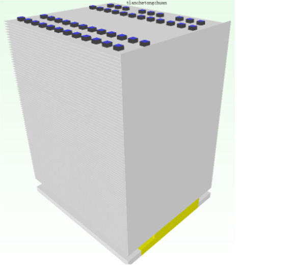 Heatsink parameter: Size:W236*L200*H304mm Fin : Thick:0.6mm Space between teeth:3.0mm Teeth number:77fins Heat pipe parameter: D8 sintered tube or fibre tube; Use 24pcs U-shaped heat pipes (one-layer layout) 4258 low temperature solder paste is used for welding; Substrate: AL plate + copper plate (IGBT heat source area) Use low cost and higher heat dissipation efficiency. Simulation diagram of pressure diffusion degree of section in module: 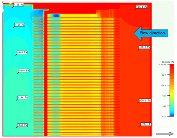 Simulation diagram of pressure diffusion degree of section in module: Simulation diagram of pressure diffusion degree of section in module: 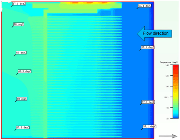 (The temperature difference between the two ends of the heat pipe is 5.7 degrees, which conforms to the actual heat pipe standard.) Simulation diagram of temperature diffusion degree of top heat pipe: 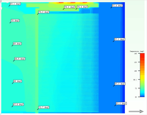 Simulation diagram of temperature diffusion degree of bottom heat pipe: 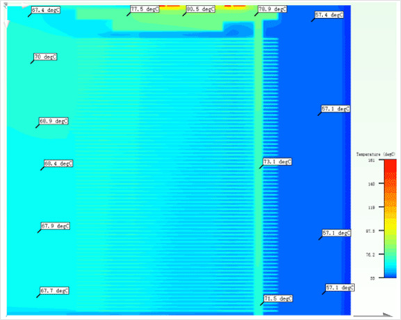 (The temperature difference between the two ends of the heat pipe is 9℃, which is slightly higher than the actual, and the actual performance of the heat pipe will be compared with the analysis setIt must be good.) Simulation diagram of temperature diffusion degree of heat pipe at the bottom of heatsink: 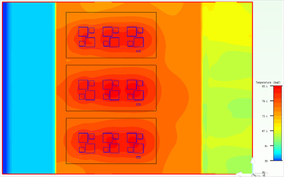 (The actual air inlet temperature of the radiator is ~57.1℃, and the maximum temperature of the radiator bottom plate is 85.1℃.Theoretical analysis of temperature rise 28℃.) NTC module temperature diffusion degree simulation diagram: 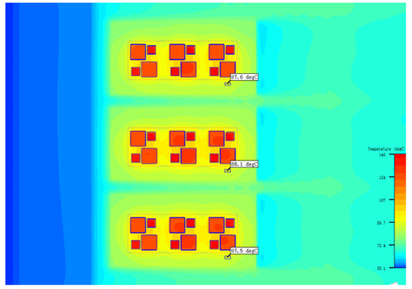 (The temperature difference between the two ends of the heat pipe is 9℃, which is slightly higher than the actual, and the actual performance of the heat pipe will be compared with the analysis Must be good.) Summary of simulation data of photovoltaic inverter heat dissipation scheme:
Assume that the incoming air temperature is 55⁰C and 57.1⁰C after reactance. Assume that 0.15mm (K=3W/m*K) is used as the thermal conductivity medium |